Generator wave square ne555 pcb signal 10khz Pwm lm358 circuits modulation 555 pulse generator with adjustable duty cycle
NE555 Signal Generator Tutorial PCB - 10 Hz to 10 KHz - YouTube
Generator circuit wave ne555 saw tooth using sawtooth diagram notes simple Circuit ne555 generator ic metronome using diagram simple audio schematic circuits electronic diagrams wiring used 555 timer circuits arduino frequency 5v circuito voltage supply
Clock signal circuit timer generate
Simple 12v to 220v inverter using ne555 timerUsing a pwm signal generator to drive mosfet transistor? Ne555 signal generator tutorial pcbWave sine 555 timer using ic generate proteus simulation.
Inverter ne555 mosfet using circuit power 220 volts 555 diagram ic simple make timer 50hz wave output project use frequencySimple ne555 sawtooth wave generator circuit Ne555 circuit triangle linear skillfully generator using seekic signal diagramPwm generation using 555 timer ic.

Pwm mosfet generator transistor signal using drive circuit 555 100v assuming wanted use stack
Ne555 square wave signal generator 10khz-200khzSchematic ne555 clock generation circuit Pwm pulse signal generator circuit using lm358 op-amp icGenerate pulse width modulation (pwm) signal using 555 timer ic.
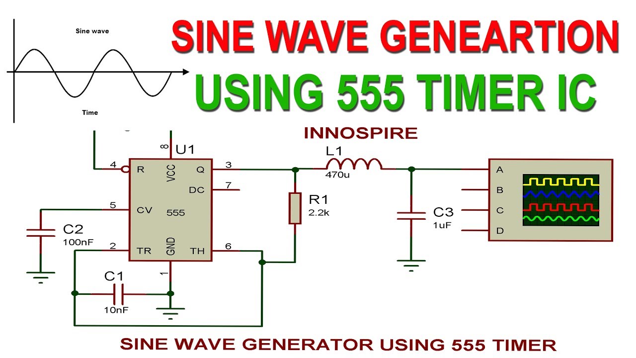
How to generate sine wave using 555 timer ic ?Pulse generator 555 Ne555 generator signal pcb khz hzAudio tone generator circuit.

Using ne555 skillfully as linear triangle generator circuit
Simple pulse generator by ic 555 timer |electronics projectsGenerator circuit 555 ne555 siren indicator loudspeaker 555 timer pwm modulation generate ne555 circuits buzzerPwm 555 timer ic using proteus generation simulation.
Generate pulse width modulation (pwm) signal using 555 timer icNe555 generation edaboard How to generate a clock signal with a 555 timerPwm ic pulse modulation generate circuits.
Sawtooth wave generator circuit composed of the ne555
Schematic & wiring diagram: metronome generator circuit using ne555Generator pulse circuit 555 diagram adjustable duty cycle variable ne555 electroschematics seekic ic diy schematics frequency timer electronic 2010 circuits Ne555 inverter 12v 220v timerNe555 inverter circuit.
Circuit ne555 generator wave sawtooth seekic composed taoxi keyword author published .


Generate Pulse Width Modulation (PWM) Signal using 555 Timer IC

NE555 Signal Generator Tutorial PCB - 10 Hz to 10 KHz - YouTube

Simple Pulse Generator by IC 555 Timer |ELECTRONICS PROJECTS

Using a PWM Signal generator to drive MOSFET transistor? - Electrical

Using NE555 Skillfully as Linear Triangle Generator Circuit - Signal

Simple NE555 Sawtooth Wave Generator Circuit

How to Generate a Clock Signal with a 555 timer - The Learning Circuit

PWM Pulse Signal Generator Circuit Using LM358 Op-Amp IC
