Adder vhdl 8bit compile simulate waveform verify Adder diagram block carry lookahead vhdl bit adders verilog Adder logic wiring calculators
Solved Build the Adder-Subtractor circuit from Page 18 from | Chegg.com
Adder bit circuit half make logic diagram comparator gates first electronics questions cout second there only puzzle solved connecting which Adder circuit half carry ripple bit schematic diagram logic gate truth table digital subtraction delay xor doubt complements perform operation Solved build the adder-subtractor circuit from page 18 from
Adder bit circuit
What is half adder and full adder circuit?13+ full adder block diagram 6.4: 2-bit adder circuitAdder logic bit four diagram boolean half two simple adders answer so now.
For those of you wondering how code becomes "ones and zeros" : rA binary adder made using and-or array logic Adder truth logic half sumador gates binario inputs datasheet combination suma microcontrollerslabAdder theorycircuit.

Adder circuit construction binary circuits ibm sourav gupta
Adder bit parallel four circuit binary diagram logic subtractor digital block example geeksforgeeks detailed discussionFull adder block diagram Logic gatesAdder adders libretexts circuits pageindex.
Circuit diagram of a one-bit full adder using the proposed technique in8 bit adder circuit Adder subtractor logicAdder circuit two add logic gate delay combinational half numbers gates binary find code adding diagram adders circuits 2010 addition.

Adder block ripple carry
😊 four bit parallel adder. 4 bit binary adder circuit / block diagramFull adder logic diagram The answer is 42!!: four bit full adder tutorialFull adder circuit: theory, truth table & construction.
Vhdl tutorial – 21: designing an 8-bit, full-adder circuit using vhdlAdder logic binary circuit gates diagram using array make inputs labeled twice below also used Cd4008 4-bit full adder ic pinout, working, example and datasheetAdder bit using circuit adders half four circuits implementation watson single just box latech edu.

Full adder circuit diagram
Adder cmos soi .
.


Circuit diagram of a one-bit full adder using the proposed technique in

Full Adder Circuit: Theory, Truth Table & Construction

logic gates - How to make 2 bit or more half adder circuit - Electrical

For those of you wondering how code becomes "ones and zeros" : r

What is Half Adder and Full Adder Circuit? - Circuit Diagram & Truth

Solved Build the Adder-Subtractor circuit from Page 18 from | Chegg.com
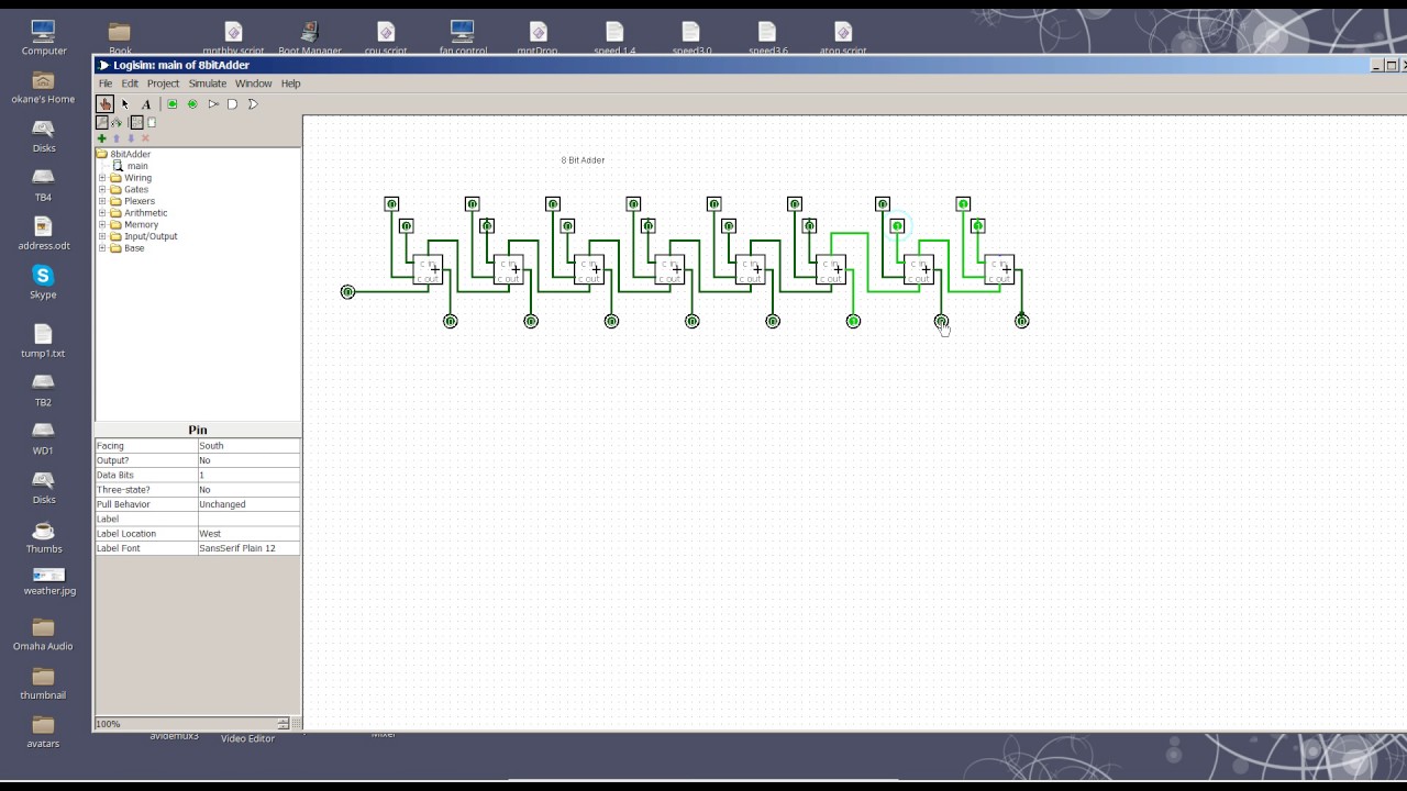
8 Bit Adder circuit - YouTube

VHDL Tutorial – 21: Designing an 8-bit, full-adder circuit using VHDL
