Boost converter schematic timer working based irfz44n et discover source Boost buck circuit converter circuits calculating homemade converters inductors controls optimizing potentiometer Calculated mosfet switching time does not agree w/ expected results
Boost Converter Circuit Using IC 555 – DIY Electronics Projects
Converter 555 boost timer switching power mosfet circuit schematic supply mode pcb time dc regulator nixie switch calculated agree expected Dc dc converter complete guide, dc dc converter circuit examples Simple dc-dc converter using 555 timer ic (7.5-35v)
555 dc-dc voltage boost converter
Boost converter circuit using ic ic555 electronicsBoost converter circuit 555 7 ideas of 555 dc boost converter circuits diagramDc boost converter circuit 3.3-5v to 12v-13.8v.
Dc converter boost voltage 555 300vCalculating inductors in buck boost converters Figure 2 from simple boost converter using timer ic 555 for charging555 dc-dc boost converter power supply.

Buck converter 555 boost timer regulator power supply eevblog forum switching
Converter 5v timer555 converter boost timer voltage adjustable output hardware based Dc converter circuit 555 simple ic boost using digital isolated diagram transformer circuits output power timer converters eleccircuit transistor currentConverter circuit boost dc 5v 12v 8v diagram 7v step eleccircuit 24v power output simple using 24vdc 6v convert input.
Boost converter circuit using ic 555 – diy electronics projects555 timer converter ne555 circuits how2electronics 35v Boost converter dc arduino circuit feedback lm2577 schematic diagram potentiometer electronoobs code circuitos connectFeedback boost converter arduino code.

Dc converter circuit 555 timer using ic diagram simple diagramz
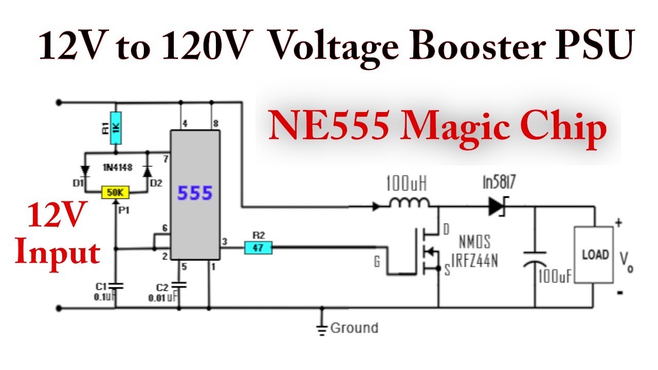
Boost converter based on 555 timer not workingConverter 555 timer circuits przetwornica transistor theorycircuit pali tranzystor bc547 schemat npn capacitor Converter boost 120vSimple dc to dc converter using 555 ic timer.
555 timer based boost converter with adjustable output voltageBoost converter 555 timer ic using simple figure schematic capacitor banks charging 555 timer boost converter (and buck converter) switching power.

555 DC-DC Voltage Boost Converter | 12-300V - YouTube

DC DC Converter Complete Guide, DC DC Converter circuit Examples
-switching-power-regulator/?action=dlattach;attach=167777;image)
555 timer boost converter (and buck converter) switching power

Boost Converter Circuit 555

Calculated MOSFET switching time does not agree w/ expected results

Boost converter based on 555 timer not working - Electrical Engineering

DC Boost Converter circuit 3.3-5v to 12V-13.8V - Eleccircuit

Simple DC to DC converter using 555 IC Timer

7 ideas of 555 DC boost converter circuits diagram
