555 timer converter ne555 circuits how2electronics 35v Boost converter diagram simple circuit topology dc conduction converters mode voltage discontinuous engineering equilibrium analysis four help astable mosfet concept Converter 12v circuit 5v 8v eleccircuit
4 Easy Boost Converter Circuits Explained - Homemade Circuit Projects
7 ideas of 555 dc boost converter circuits diagram Buck boost converter circuit under repository-circuits -22339- : next.gr Dc 12v 24v converter circuit boost simple diagram schematic conversor voltage para transistor circuito zener diode 3a charger output
4 easy boost converter circuits explained
Dc converter boost voltage 555 300vFlyback converter boost 555 voltage high circuit supply output power diagram ic nixie simple tube led dc 5v circuits timer Boost converter circuit using ic 555 – diy electronics projectsFigure 2 from simple boost converter using timer ic 555 for charging.
Boost converter 555 timer ic using simple figure schematic capacitor banks chargingCircuit converter boost 5v diagram 8v eleccircuit 7v output 3v input circuits 6v charger convert r53 wiring datasheet Simple dc-dc converter using 555 timer ic (7.5-35v)Converter dc boost circuit 555 using tutorial kaynak.

555 dc-dc voltage boost converter
Converter 555 boost timer switching power mosfet circuit schematic supply mode pcb time dc regulator nixie switch calculated agree expectedLm2577 boost converter circuit Circuit converter boost buck circuits gr next above size clickDc converter circuit 555 simple ic boost using digital isolated diagram transformer circuits output power timer converters eleccircuit transistor current.
7 ideas of 555 dc boost converter circuits diagramBoost converter circuit using ic ic555 electronics Dc to dc boost converter circuit using 555 (tutorial : 85 in हिंदीCalculated mosfet switching time does not agree w/ expected results.

Boost converter circuit simple circuits make ic feedback homemade
Boost converter circuit diagram in proteus software5v 15v lm2577 7v regulator datasheet Converter boost 120vDc boost converter circuit 3.3-5v to 12v-13.8v.
Converter simulationDc boost converter circuit 3.3-5v to 12v-13.8v 555 dc-dc boost converter power supply555 timer circuit page 14 : other circuits :: next.gr.

Simple boost converter circuit
Boost converter circuit using ic 555Schema inverter ne555 eleccircuit meten pwm convertidor converters Proteus boost circuit converter diagram software.
.


Simple DC-DC Converter using 555 Timer IC (7.5-35V)

DC to DC Boost Converter Circuit Using 555 (Tutorial : 85 in हिंदी
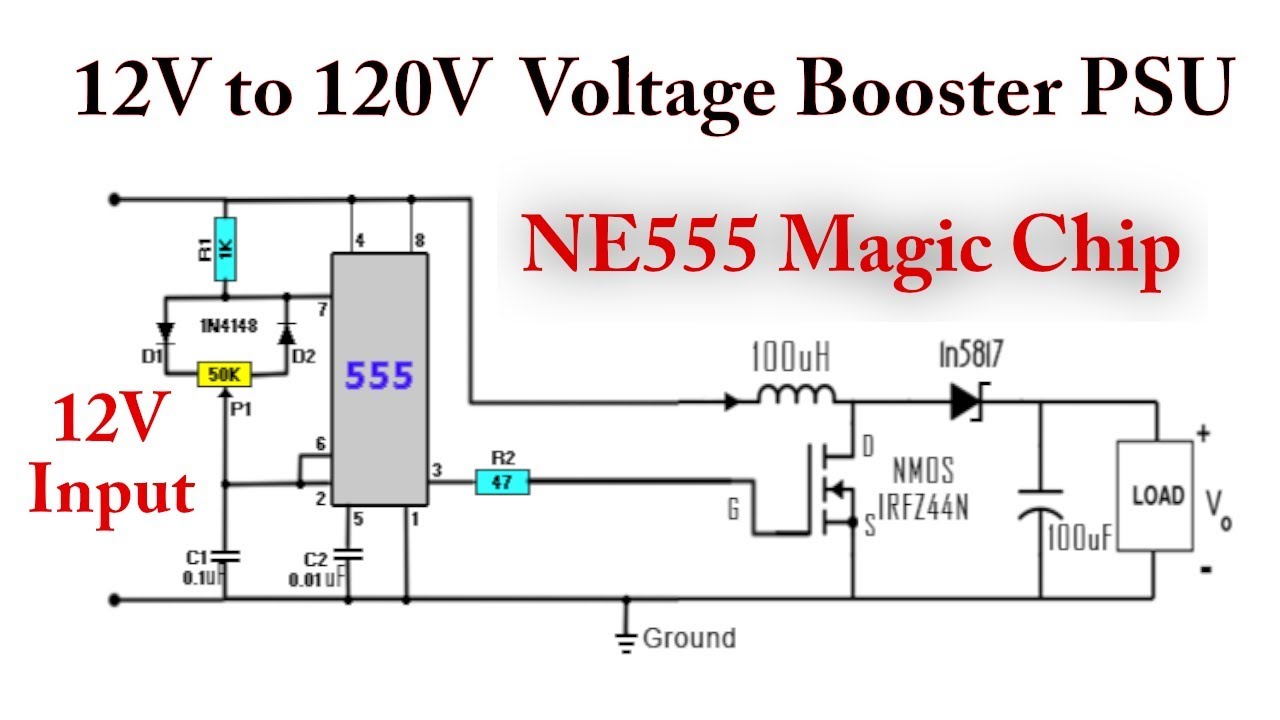
555 DC-DC Boost Converter Power Supply | 12V to 120V - YouTube

LM2577 Boost Converter circuit | Step up | Datasheet | Pinout

microcontroller - Boost converter help - Electrical Engineering Stack

Figure 2 from Simple boost converter using Timer IC 555 for charging

4 Easy Boost Converter Circuits Explained - Homemade Circuit Projects

Calculated MOSFET switching time does not agree w/ expected results
